Through-hole vs SMD soldering: tools, access and learning curve
Through-hole soldering is usually the simpler starting point because the component leads pass through the PCB, giving you clear access and a visible joint; SMD soldering places parts on the board surface, so you work with smaller pads, tighter spacing and more careful inspection and rework.
Answer the difference in the opening
That difference shapes almost everything else: through-hole work suits larger parts and straightforward hand tools, while SMD work often calls for finer tips, tweezers, flux and, for some rework jobs, hot air rather than an iron alone. SparkFun’s through-hole soldering guide lays out the basic pad-and-lead sequence, and its hot-air rework guide shows how hot air is used for surface-mount handling and rework.
Show how component mounting changes access to joints
Through-hole leads extend through the board, so you can usually see the joint and reach it from the component side or the solder side. SMD parts sit directly on pads, which can hide the joint under the package or crowd nearby parts, making access more dependent on magnification and clean pad preparation.
Compare typical hand tools and hot-air use without universal settings
For through-hole soldering, a temperature-controlled iron, solder, cutters, and sometimes braid or a pump cover most jobs. For SMD, fine tweezers, flux, a suitable iron tip and magnification are common; hot air can help with rework or with lifting and repositioning parts, but it is not mandatory for every SMD task. Do not copy a single temperature across alloys, components or boards: use the component datasheet, solder choice and board instructions first.
Explain inspection and rework differences
Through-hole joints are usually checked by looking for a smooth, complete fillet around the lead; SMD inspection is more about pad coverage, alignment and whether bridges or lifted parts are present. Rework also differs: through-hole faults may be corrected with an iron, braid or a pump, while SMD faults may need more local heating, more flux and careful part handling.
Give a beginner task-selection table
| Task | Better starting method | Why it fits |
|---|---|---|
| First practice joints | Through-hole | The lead, pad and fillet are easier to see and inspect. |
| Headers, connectors and large leads | Through-hole | There is more room to place the part and form the joint. |
| Small passives on a crowded board | SMD | The parts are designed for surface pads and compact layouts. |
| Board touch-up after removal or repair | Depends on the part | Choose the method that matches the package, pad access and board condition. |
Set limits for fine-pitch, heat-sensitive and safety-critical boards
Use extra caution with fine-pitch parts, heat-sensitive components and any board where failure has consequences. If the datasheet, repair guide or board documentation is unclear, stop and confirm the correct solder, temperature window, airflow and handling steps instead of guessing. Through-hole is not automatically safe, and SMD does not always require hot air.
Add an FAQ on mixed-technology boards and practice material
Can one board use both methods?
Yes. Many boards mix through-hole connectors or headers with SMD passives and ICs, so the right approach may change from one section to another.
What should I practise on?
Use scrap boards, purpose-made practice kits or other non-critical material. Aim for simple joints first, then move to smaller parts only when you can place and inspect them cleanly.
Should I start with SMD or through-hole?
Most beginners find through-hole a simpler first step because the joints are easier to see and access, but the best choice depends on the task and the board, not just the package type.
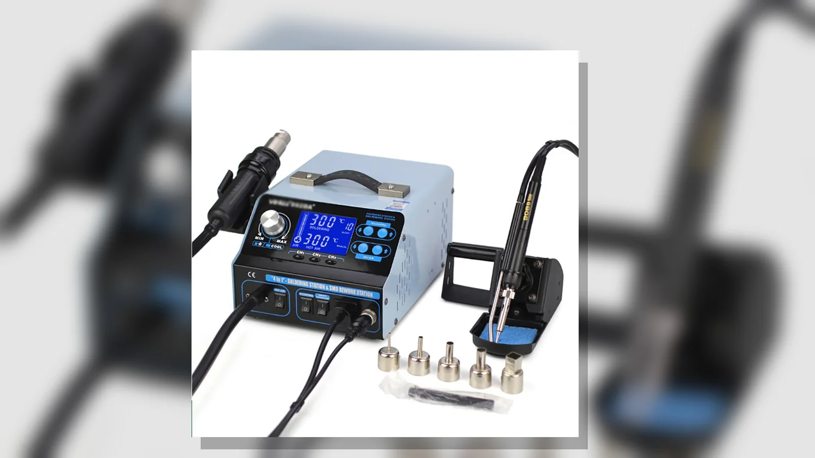
If you are comparing a combined station, see the current product details.